| |
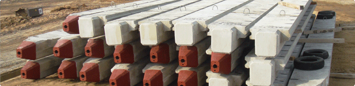
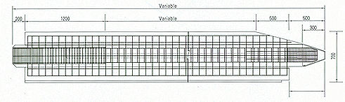
 Home > Introduction > T- Wall Pile Home > Introduction > T- Wall Pile |
| |
|
   |
| |
 |
| |
 |
| |
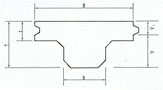
| Model |
Dimension |
Section
area |
Y1
(cm2) |
Y
(cm2) |
Moment
of
inertia of area |
Section modulus |
Crack
moment |
Unit
weight |
| B |
b |
T |
t |
Z1 |
Z2 |
TWP-250-50
|
700 |
300 |
250 |
50 |
950
|
10.4
|
14.6
|
55.268
|
3.785
|
5.314
|
4.4-5.8
|
0.238 |
TWP-250-100
|
700 |
300 |
250 |
100 |
1,150
|
9.9
|
15.1
|
55.934
|
3.704
|
5.650
|
4.4-6.3
|
0.268 |
TWP-300-100
|
700 |
300 |
300 |
100 |
1,300
|
12.0
|
18.0
|
98.533
|
5.474
|
8.211
|
6.0-6.9
|
0.325 |
TWP-350-100
|
700 |
300 |
350 |
100 |
1,450
|
14.0
|
21.0
|
155.783
|
7.418
|
11.127
|
8.1-12.0
|
0.363 |
TWP-350-150
|
700 |
300 |
350 |
150 |
1,650
|
13.86
|
21.14
|
145.618
|
7.409
|
11.300
|
8.1-12.1
|
0.413 |
TWP-400-150
|
700 |
350 |
400 |
150 |
1,925
|
16.6
|
23.4
|
256.271
|
10.962
|
15.438
|
11.1-16.5
|
0.481 |
TWP-450-150
|
700 |
350 |
450 |
150 |
2,250
|
17.5
|
27.5
|
367.510
|
13.364
|
21.000
|
13.5-22.0
|
0.563 |
TWP-450-200
|
700 |
400 |
450 |
200 |
2,400
|
19.37
|
25.63
|
394.061
|
15.375
|
20.335
|
14.7-21.6
|
0.600 |
TWP-500-150
|
700 |
400 |
500 |
150 |
2,450
|
21.8
|
28.2
|
537.605
|
19.064
|
24.661
|
17.9-24.3
|
0.613 |
| TWP-500-200 |
700 |
400 |
500 |
200 |
2,600 |
21.5 |
28.5 |
540.510 |
18.966 |
25.140 |
17.8-26.5 |
0.650 |
|
|
| |
 |
| |
 |
| |
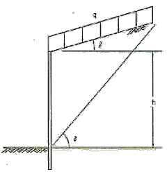
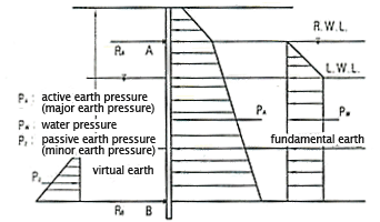
占쏙옙 Sand Soil
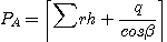 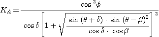
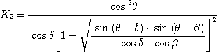
PA = PO : Major (minor) earth pressure (t/m2)
 :Frictional Angle(占쏙옙) inside soil :Frictional Angle(占쏙옙) inside soil
r : Unit weight of soil
h: Height of wall (m)
KA,KP : Coefficient of major (minor) earth pressure
 :Angle between earth占쏙옙s surface and horizon :Angle between earth占쏙옙s surface and horizon
 : Friction Angle (占쏙옙) of wall : Friction Angle (占쏙옙) of wall
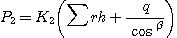
q: load on the top(t/m2)
|
占쏙옙 Clayey soil
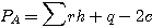
c:adhesive power
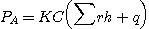
KC: Consolidation coefficient
PP =  r h+q+2c ) r h+q+2c ) |

|
 |
 |
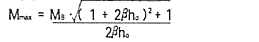
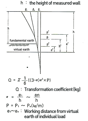
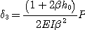
Maximum moment is calculated by Y.L Chang formula.
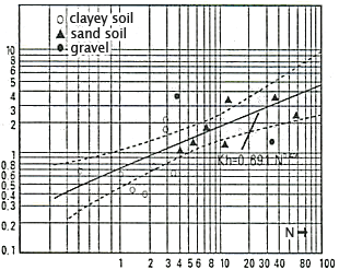
[Relationship between coefficient of
earth reaction and N] |
|
Embedded depth of pile is calculated by following:
D = 
D : The embedded depth of pile(m)
exp [-tan-1 ] ]
=4 
:Coefficient of characteristics
Kh: Coefficient of earth reaction on horizontal direction (kg/占쏙옙)
B: Unit width(=100cm)
E : elasticity coefficient of pile
In the case of P.C
 28 = 400kg/占쏙옙, E = 350,000kg/占쏙옙) 28 = 400kg/占쏙옙, E = 350,000kg/占쏙옙)
28 = 500kg/占쏙옙, E = 400,000kg/占쏙옙)
占쏙옙: Moment of Inertia of Area (cm4/m)
|
|
|
 |
|
占쏙옙 Decision of pre-stress
Pre-stress is decided to satisfy following formula
|
M : maximum distortion moment of measurement
N : maximum axial force of design
(compressive force is major, and tensile power is minor)
N : minimum axial force of design
(compressive force is major and tensile power is minor)
le : Calculated moment of inertia of area
Ac: Cross section of pile
Ye : Distance between center and compressive part
Ye': Distance between center and tensile part
 ce: Valid pre-stress
 ca: Allowed stress of distortive compression of concrete
Ordinary time : -20kg/占쏙옙
Earthquake : -40kg /占쏙옙
 ca : Allowed stress of distortive compression of concrete
Ordinary time : 170kg/占쏙옙
Earthquake : 250kg/占쏙옙
However, ck = 500kg/占쏙옙
占쏙옙 Sectional stress before cracking
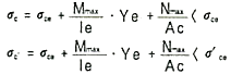
3. Moment of cracking distortion
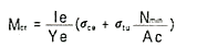
Mcr = Moment of cracking distortion
 tu= the strength of distortive tensile of concrete < 0
 |
|
|
 |
 |
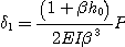
The displacement of head is calculated by following equation:
 =
=  1+
1+ 2+
2+ 3
3
 1:The displacement in virtual earth (cm)
 2:The displacement by cracking in virtual earth (cm)
 3:Deflection of vertical hem of Camtel lever beam by taking distributional rate of rear earth pressure as load with fixed virtual earth (cm)

|
占쏙옙 Ordinary
S.
F:1.5
C: adhesive power on active section (t/m2)
 : Partition circular arc length on active section (m)
W: weight (t/m2)
U: water pressure of gap (t/m2)

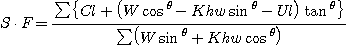
S.F = 1. 2 |
|
|
| |
 |
| |
 |
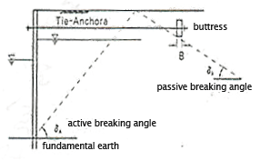
| Following the calculation for self-support wall pile |
|
|
 |
|
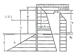
Mp  F
F M A
M A
MA = PA
 A+ PW
A+ PW  W
W
MP = PP
 P
P |
MP : The moment concerning connection point of tie anchor by minor earth pressure (t m/m)
m/m)
MA :The moment concerning connection point of tie anchor by major earth pressure and remained water pressure
D:Calculated embedded depth
F:Safety Factor
Soil Type |
Safety Factor |
Ordinary |
Earthquake |
Sandy soil |
1.5
|
1.2 |
Clayey soil |
1.2 |
1.2 |
|
|
 |
 |
占쏙옙 Calculating spot reactive force and distortive moment by considering spot A and B simple beam.
占쏙옙 Location of virtual spot
Type of soil |
Depth from base earth |
High quality sand |
0.1H |
Normal sand |
0.2H |
Clay
|
0.3H |
|
The tensile force on tie anchor is calculated by following:
T = RA 


T : tensile force of tie-anchor
RA : spot reactive force of spotA (t/m)
 : Connection interval of tie-anchor (m)
 : the tilt angle of tie-anchor against horizontal line (占쏙옙) : the tilt angle of tie-anchor against horizontal line (占쏙옙) |
|
|
 |
 |
The maximum distortive moment of wailing is calculated by following:
M =
= 
M : the maximum moment of wailing (t/m)
T : tensile force of tie-anchor (t)
 : connection interval of tensile force of tie-anchor (m)
 |
= 
F : Safety factor (ordinary: 2.5, earthquake: 2.0)
EP : minor earth pressure on buttress (t/m)
AP: reactive force of connection spot of tie-anchor (t/m)
EA : major earth pressure on buttress (t/m)
 |
|
|
|
 |
 |
 |
占쏙옙 MATERIALS TABLE-1
Component |
Speclitcation |
Symbol |
Steel Strand |
Uncoated Stress Relieved
Steel Wire and Strand for
Prestressed Concrete |
KSD3509
3510 |
Anchor Fitting |
Chromium Molybdenum Steel KSD3711 |
SCM435 |
Coating |
High Density Polyethylen |
P.E |
Nut |
Carbon Steel for Machine Structural |
S.45C |
|
|
|
|